NM Type Rubber Coupling
A compact two-hub flexible coupling family with an NBR buffer element, catalogue nominal torque from 5 to 1,000 N·m and maximum bores from 19 to 95 mm.
Technical data appears before marketing claims.
The table below is transcribed only from the single supplied EVER-POWER catalogue page. Values are reproduced in the printed units. No competitor ratings, inferred materials for the hubs, certificate claims or interchangeability claims have been added.
NM50–NM214 dimensions and ratings
Evidence class: catalogue_exact. Nominal torque, limited rotational speed, D, D₁, maximum shaft diameter dmax, hub length L, gap S, radial offset ΔY and angular offset Δα are copied from the approved source region.
| Type | Nominal torque N·m |
Limited speed rpm |
D mm |
D₁ mm |
d max mm |
L mm |
S mm |
Radial ΔY mm |
Angular Δα ° |
|---|---|---|---|---|---|---|---|---|---|
| NM50 | 5 | 3000 | 50 | 33 | 19 | 25 | 2 ± 0.5 | 0.03 | 3.0 |
| NM67 | 13 | 3000 | 67 | 46 | 28 | 30 | 2.5 ± 0.5 | 0.03 | 3.0 |
| NM82 | 28 | 3000 | 82 | 53 | 32 | 40 | 3.0 ± 1.0 | 0.05 | 3.0 |
| NM97 | 45 | 3000 | 97 | 69 | 42 | 50 | 3.0 ± 1.0 | 0.05 | 2.5 |
| NM112 | 70 | 3000 | 112 | 79 | 48 | 60 | 3.5 ± 1.0 | 0.07 | 2.5 |
| NM128 | 140 | 3000 | 128 | 90 | 55 | 70 | 3.5 ± 1.0 | 0.07 | 2.5 |
| NM148 | 280 | 3000 | 148 | 107 | 65 | 80 | 3.5 ± 1.0 | 0.07 | 2.0 |
| NM168 | 500 | 3000 | 168 | 124 | 75 | 90 | 3.5 ± 1.5 | 0.10 | 2.0 |
| NM194 | 840 | 1500 | 194 | 140 | 85 | 100 | 3.5 ± 1.5 | 0.10 | 2.0 |
| NM214 | 1000 | 1500 | 214 | 157 | 95 | 110 | 4.0 ± 2.0 | 0.10 | 2.0 |
A blank value would be shown as “Not stated”; this table contains no blank source cells. D and D₁ are drawing dimensions. “d max” is a bore ceiling, not an automatic finished-bore recommendation.
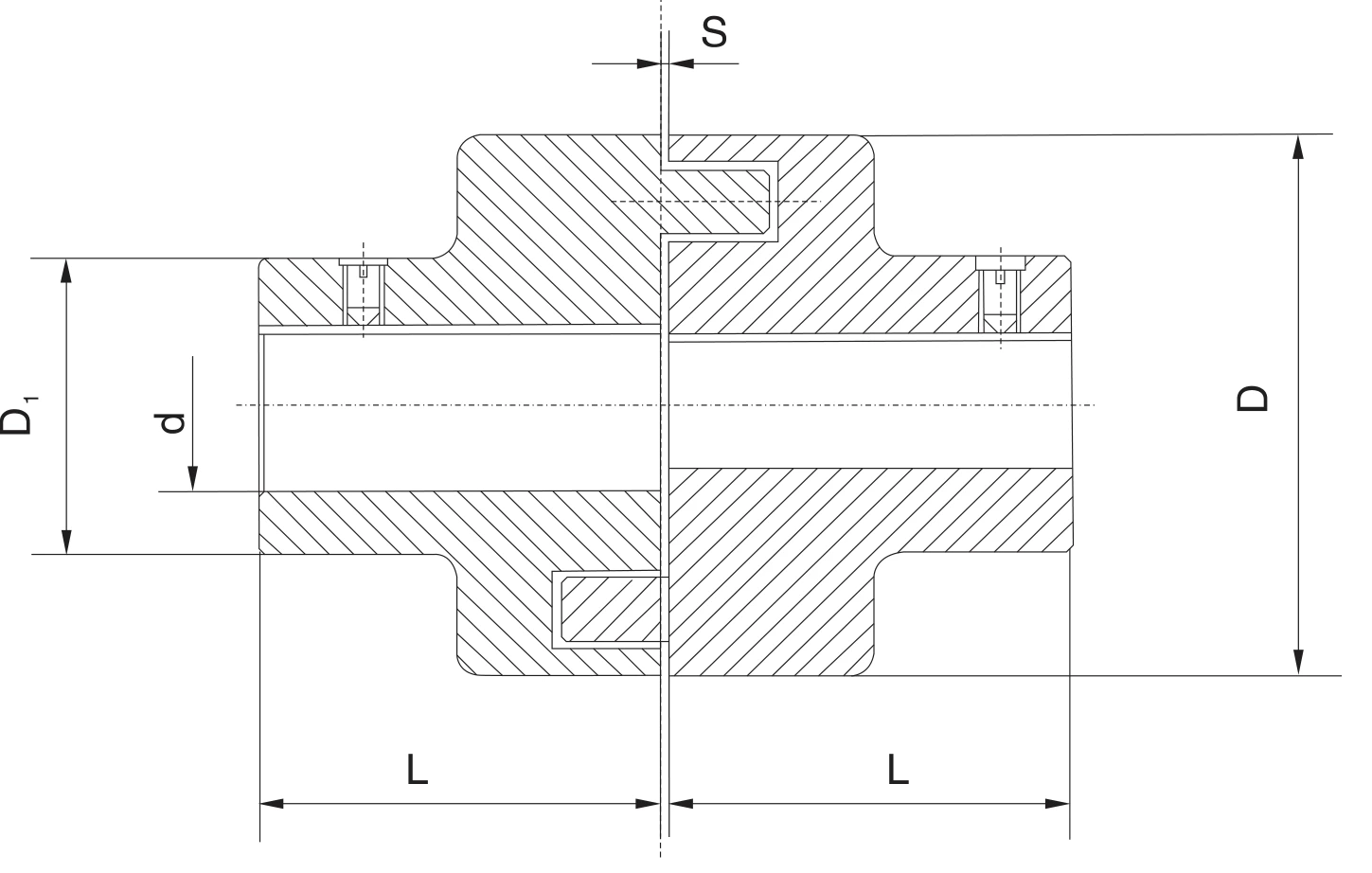
Catalogue dimension drawing, page 1. Full geometry is retained; click for the 1449 px source crop.
Match the drawing to both shafts.
D is the overall coupling outside diameter. D₁ is the smaller hub-body diameter shown at the shaft-entry side. d is the finished bore, limited by dmax in the table. L is shown for each coupling half. S is the nominal separation at the centre with its printed tolerance.
The marking example on the source is NM67-24/25: model NM67, driving end Ø24 mm and driven end Ø25 mm. This demonstrates asymmetric bore marking but does not state the keyway dimensions or bore tolerances. Those remain order-specific.
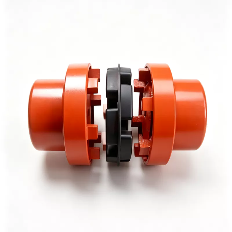
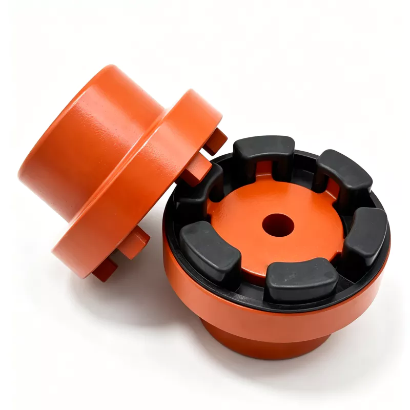
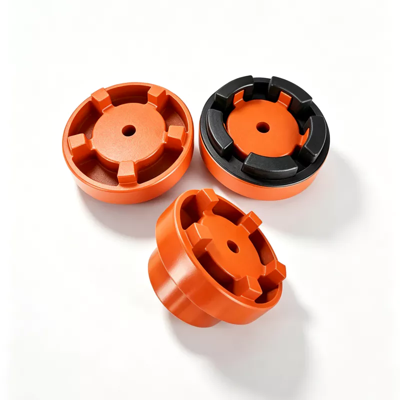
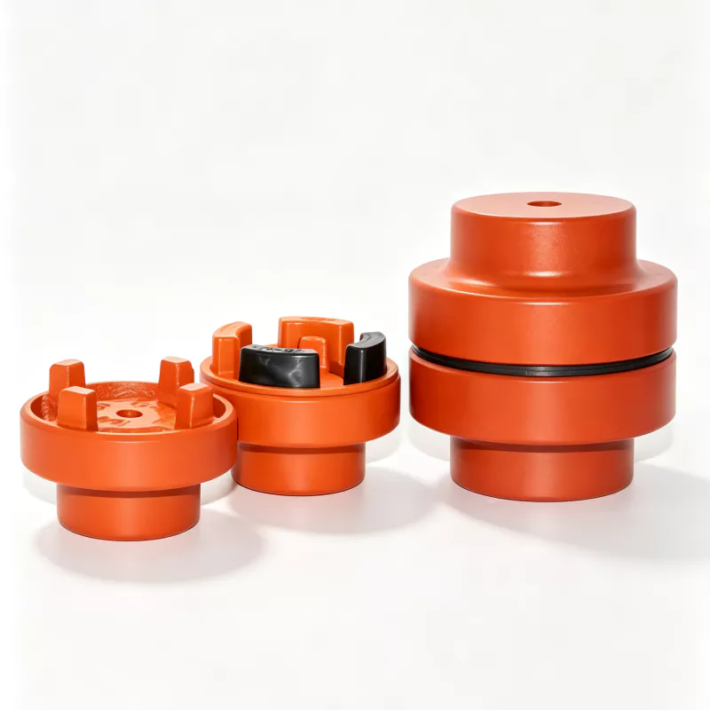
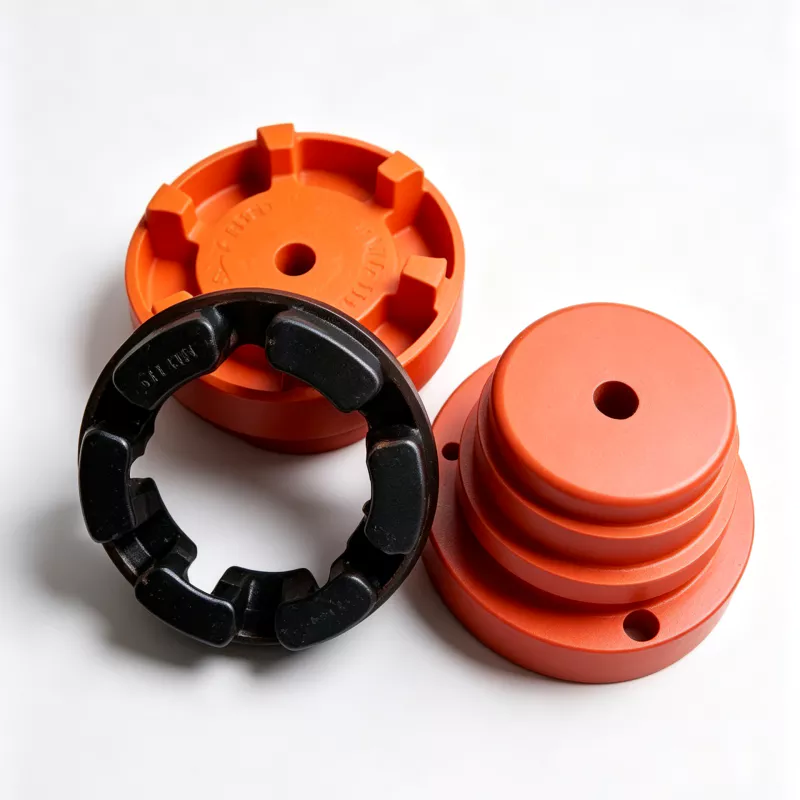
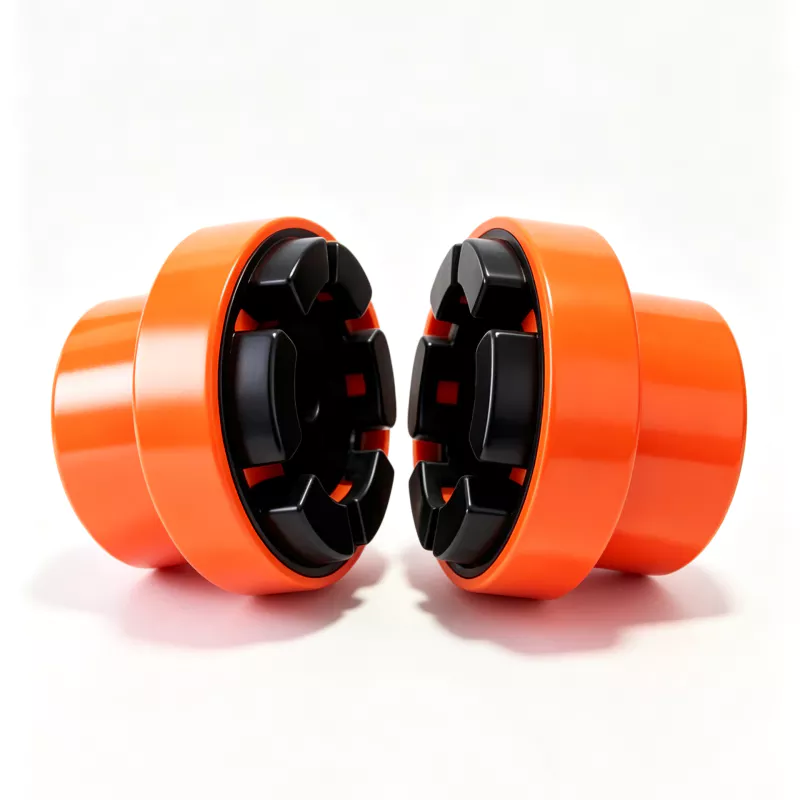
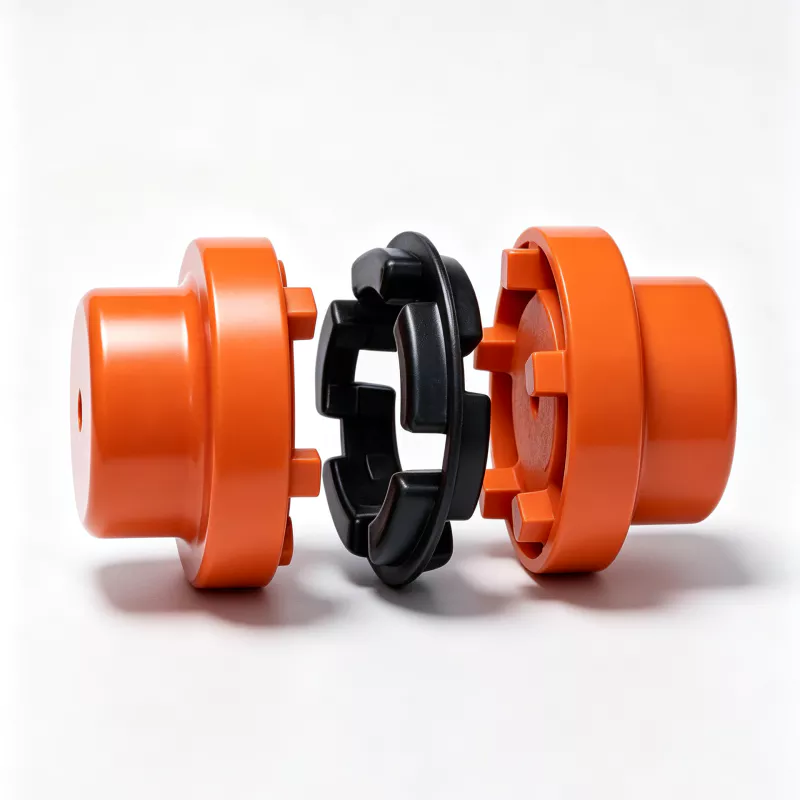
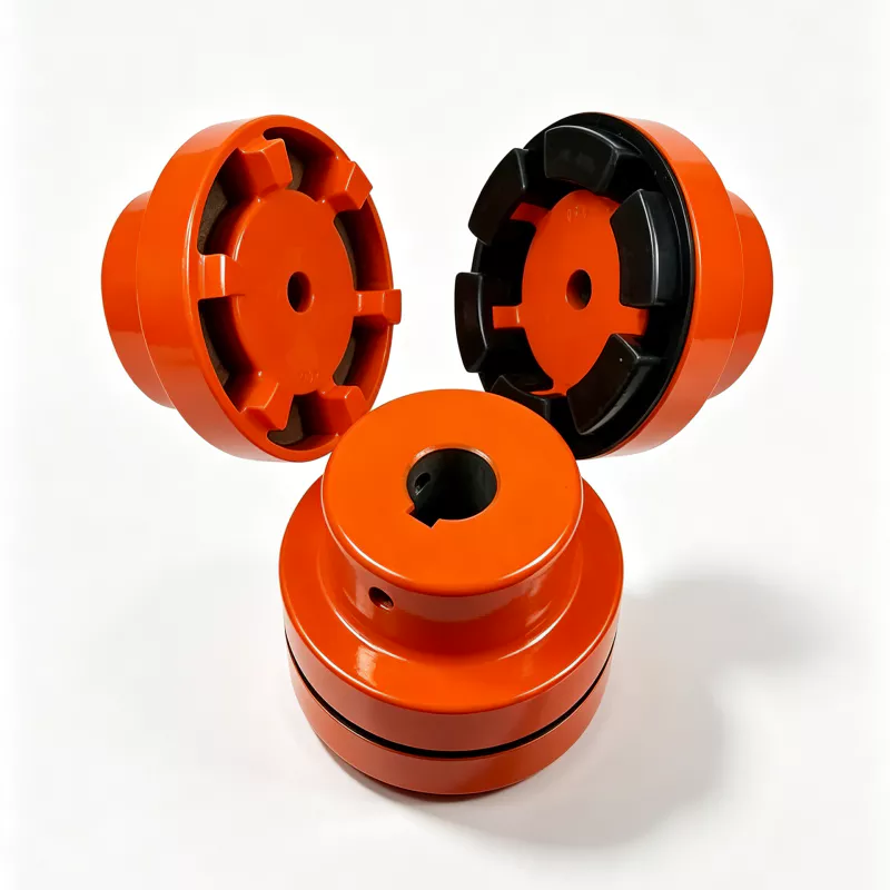
NM coupling construction from multiple views.
These product photographs show the orange metal hubs, interlocking drive lugs and black flexible element. They supplement the catalogue drawing; they do not define the finished bore, keyway or production dimensions.
Selection is more than choosing the next torque row.
The first screening step is continuous transmitted torque. If motor power and operating speed are known, a useful derived estimate is T = 9550 × P / n, where T is N·m, P is kW and n is rpm. That estimate is not the whole selection because starting torque, driven-machine inertia, reversals, jams, cyclic loading and control strategy can produce peaks above steady-state torque. State both continuous and credible peak torque on the RFQ.
Current official coupling-selection guidance from NBK follows the same engineering sequence at a general-method level: choose rated torque above system load torque, then verify maximum bore and rotational frequency, and account for the effect of temperature on rubber or resin elements. Those statements are web context, not NM catalogue ratings. This NM page therefore does not apply NBK temperature factors to EVER-POWER models. Instead, temperature is requested for engineering review because the supplied NM source does not state a working-temperature range.
The maximum bore column is a geometric and strength boundary. A bore at the printed maximum leaves less hub section around the shaft. A deep keyway, unusual tolerance, large key, sharp corner or high reversing load can change the hub stress. For that reason, a request such as “NM148, 65 mm bore” needs the shaft drawing, key standard and duty, even though 65 mm appears as dmax.
Torque and speed boundary
NM50 through NM168 carry a printed limited speed of 3,000 rpm. NM194 and NM214 are limited to 1,500 rpm. Do not extrapolate a higher limit because the connected motor can run faster. Coupling balance, bore machining, key geometry, runout, guard design and connected rotor dynamics all matter at speed. If the actual speed approaches the published limit, include acceleration, overspeed scenario and balancing expectations in the inquiry.
Misalignment is capacity, not an installation target
The catalogue gives radial offset and angular offset values. These values should be treated as maximum published allowances, not a reason to leave shafts visibly out of line. Better initial alignment normally reduces alternating element strain, bearing reaction loads, vibration and heat. Current NBK installation guidance notes that excessive misalignment can cause vibration and shortened coupling life and recommends aligning within the selected product's own published values. The source also discusses combined misalignment, but because that rule belongs to NBK products it is not imported as an NM rating. When radial, angular and axial effects coexist on an NM application, provide the measured values for project review.
Element environment
The catalogue explicitly names NBR and says the buffer element is oil resistant and wear resistant. NBR is not a universal answer to every fluid, outdoor climate or process chemical. Compatibility depends on the exact oil or chemical, concentration, temperature, immersion versus splash, ozone, sunlight and cleaning regime. An exposed washdown line, outdoor aggregate conveyor, paint plant and enclosed clean machine have different risks. The RFQ should identify those conditions rather than relying on a generic “rubber coupling” description.
Installation interfaces
Measure each shaft separately. Confirm diameter, tolerance, usable engagement length, keyway width and depth, key position, shoulder clearance and whether the shaft can move axially during installation. The printed L dimension is the hub length shown on the source drawing. A shaft that is too short may not develop adequate engagement; a shaft inserted too far may contact the opposite half or eliminate the intended centre gap. Verify S after the hubs are positioned and before the guard is closed.
The two machine shafts should be supported independently. The flexible element is not a bearing and should not be expected to correct soft foot, a bent shaft, loose bearings or a moving foundation. Perform alignment after tightening the machine feet and pipe connections, then recheck after the first controlled run because piping strain and structural settling can move the equipment.
Guarding and safe access
A rotating coupling must be integrated into the machine's risk controls. In the United States, OSHA 29 CFR 1910.219 addresses collars and couplings and requires construction that does not present hazards from projecting fasteners or rotating surfaces. Other target markets have their own machinery frameworks. This site provides procurement context, not a declaration that a coupling alone makes a machine compliant. The machine designer, integrator and employer remain responsible for the guard, risk assessment, instructions and lockout process.
Commissioning record
Record final bore and key data, shaft separation, radial and angular readings, fastener method, runout, guard clearance and no-load observations. Start at a controlled condition if the machine design permits, listen for periodic beating, and monitor vibration. Stop if the coupling runs abnormally. After the initial service interval, inspect for element cracking, extrusion, hardening, swelling, oil attack, loose hubs, fretting or unexpected dust.
Maintenance and replacement
The catalogue's “no lubrication, maintenance-free” statement means no coupling lubricant is required; it does not remove the need for condition inspection. Build inspection frequency from duty severity, start frequency, access, environment and consequence of failure. Keep the exact coupling marking and both bore sizes in the maintenance record. If replacing an installed unit, photograph the assembly before removal, measure the shafts and centre gap, and do not assume an old or third-party NM marking has identical dimensions.
RFQ and drawing-approval checklist
- Driver type, rated power, base speed and maximum speed
- Continuous torque, start torque, peak torque and starts per hour
- Driven equipment and shock or jam behavior
- Driving and driven shaft diameters, tolerances and engagement lengths
- Keyway standard, key dimensions and any set-screw requirement
- Measured radial, angular and axial movement
- Ambient and local element temperature
- Oil, chemical, ozone, sunlight, dust or washdown exposure
- Guard envelope, access limitation and required documentation
- Quantity, destination, packaging and approved drawing contact
Technical answers grounded in the supplied page.
How do I read NM67-24/25?
The supplied catalogue uses NM67-24/25 to mean an NM67 coupling with a 24 mm bore on the driving side and a 25 mm bore on the driven side.
Is 3,000 rpm allowed for every NM size?
No. The catalogue lists 3,000 rpm through NM168 and 1,500 rpm for NM194 and NM214.
Are the listed misalignment values cumulative?
The catalogue provides radial and angular values but does not state a combined-misalignment rule. Treat simultaneous offsets conservatively and obtain engineering confirmation.
Can the maximum bore be used automatically?
No. d max is the catalogue ceiling. Keyway depth, hub strength, shaft fit, torque and manufacturing method still need review.
Is the NBR element suitable for every chemical?
No. The source states oil and wear resistance, not universal chemical compatibility. Provide fluid, concentration, temperature and exposure duration.
What controls production?
The approved order drawing and commercial specification control production. The catalogue page is selection evidence, not a substitute for a project drawing.